
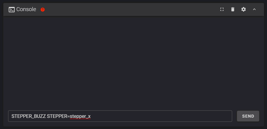
Stepper Motor Check
To verify that each stepper motor is operating correctly, send an appropriate STEPPER_BUZZ command, such as:
STEPPER_BUZZ STEPPER=stepper_x
The STEPPER_BUZZ command will cause the given stepper to move one millimeter in a positive direction and then it will return to its starting position. This movement cycle will repeat 10 times.
You will be looking for three things:
- Ensure that the motor which responds is the one you expected.
- Ensure that the motor moves cleanly: forward, pause, back, pause, repeat. Lack of movement, or vibrating or buzzing oddly are all cause for concern
- Ensure that the motor moves the correct direction first. If the movement is backwards, it is important to correct at this stage.
A single test of each motor is being used to confirm multiple aspects of its function: that the motor moves properly, that it’s the correct motor, and what direction it moves. Please make sure you confirm ALL stated expectations for each motor. You can repeat the test multiple times if needed.
Run this command for each of the motors:
| Command | Expectation |
|---|---|
| STEPPER_BUZZ STEPPER=stepper_x | The back left gantry motor will rotate clockwise first, then back counterclockwise |
| STEPPER_BUZZ STEPPER=stepper_y | The back right gantry motor will rotate clockwise first, then back counterclockwise |
| STEPPER_BUZZ STEPPER=stepper_z | the bed will move down, then back up |
| STEPPER_BUZZ STEPPER=extruder | The extruder moves. Direction will be tested later for this motor |
Troubleshooting
-
If the stepper does not move at all verify the following: the “enable_pin” and “step_pin” in your printer.cfg.
-
If the stepper motor moves but does not return to its original position then verify the “dir_pin” setting.
-
If the stepper motor oscillates in an incorrect direction, then it generally indicates that the “dir_pin” for the axis needs to be inverted. To do this, add a ‘!’ in front of the “dir_pin”. Example: “dir_pin: !PIN”
-
If the motor moves significantly more or significantly less than one millimeter then verify the
rotation_distancesetting. -
If the motor buzzes, check the stepper motor wiring.

XY Homing Check
At this point everything is ready to home X and Y.
You need to be able to quickly stop the printer in case something goes wrong (e.g. the tool head goes the wrong direction). There are a few ways of doing this:
- Use the E-stop button on the display (if installed). On the Mini12864 it is the small button underneath the main control knob. Test the button and see what happens - Klipper should shut down. The Raspberry Pi and OctoPrint/Mainsail/Fluidd should still be running but disconnected from Klipper.
- Have a computer right next to the printer with the
RESTARTorM112command already in the terminal command line. When you start homing the printer, if it goes in the wrong direction, quickly send the restart command and it will stop the printer.- As a “nuclear” option, power off the printer with the power switch if something goes wrong. This is not ideal because it may corrupt the files on the SD card and to recover would require reinstalling everything from scratch.
After a shutdown, press the FIRMWARE_RESTART button in Mainsail or Fluidd to resume normal operation
After a shutdown, press “Connect” in the upper left corner of OctoPrint. Next, in the Octoprint terminal window send a FIRMWARE_RESTART to get the printer back up and running.
Once there is a tested process for stopping the printer in case of something going wrong, you can test X and Y movement. First, send a G28 X command. This will only home X: The bed should move down slightly and then the toolhead should move to the right until it hits the X endstop.
- If the bed moves upwards before moving to the right, you must reverse your z stepper directions in the config.
- If the toolhead moves in an incorrect direction, stop it with emergency stop, take note of what direction it went, and move on to testing Y
Next, test Y: run G28 Y. The bed should move down slightly, and then the toolhead should move towards the back of the printer until it hits the Y endstop.
In a CoreXY configuration, both motors motors work together to move the printer in X or Y (think Etch A Sketch). As a result, testing X homing alone tells us very little. We must test X and Y in order to determine what (if any) adjustments are needed
If either axis does not move the toolhead in the expected or correct direction, refer to the table below to figure out how to correct it. If you need to invert the direction of one of the motors, invert the direction pin definition by adding a ! to the pin name. For example, dir_pin: PB2 would become dir_pin: !PB2. (if the entry already has a !, remove it instead). If the motors are going in directions that match the lower row of the chart, physically swap your X and Y (A and B) motor connectors at the MCU.
- [stepper x] = Motor B
- [stepper y] = Motor A
Motor Configuration Guide for the Voron V0
Z Endstop Location
V0.2
For V0.2 the Z endstop is located at the bottom of the machine. After homing Z you can use the Z_ENDSTOP_CALIBRATE command to find the correct position_endstop value automatically.
V0.0 & V0.1
The V0.0 and V0.1 uses the bed assembly to contact the Z endstop switch via an adjustable screw in the T8 nut block. Ideally the activation of that switch will be at the exact bed height at which your nozzle also reaches the bed surface. However there is a window of travel from the moment that switch is activated to the point at which that switch bottoms out, this window is about 0.6mm. As a result, calibrating Z on these printers is a 2 step process:
- Adjust the screw, so that the endstop is triggered just slightly before the nozzle hits the bed (within about 0.6mm)
- Use the
Z_ENDSTOP_CALIBRATEroutine (below) to fine tune the calibration of the endstop switch in software.
Z Endstop Calibrate
We will use a piece of copy paper to set the height of our nozzle relative to the endstop position, do this test with your nozzle cold. When the nozzle is heated, its position (relative to the bed) changes due to thermal expansion. This thermal expansion is typically around a 100 microns, which is about the same thickness as a typical piece of printer paper. The exact amount of thermal expansion isn’t crucial, just as the exact thickness of the paper isn’t crucial. Start with the assumption that the two are equal.
- Home z
- Place the piece of copy paper on the bed
- Run the
Z_ENDSTOP_CALIBRATEcommand.
- move the nozzle closer to the bed in small increments, using
TESTZ Z=commands.
- a dialog box will open that allows you to move the nozzle up and down by preset amounts.
- move the nozzle closer to the bed in small increments, using the controls in the dialog
- after each movement push the paper back and forth to check if the nozzle is in contact with the paper and to feel the amount of friction.
- Continue issuing commands until you feel a small amount of friction when testing with the paper. If too much friction is found then you can use a positive Z value to move the nozzle up.
- Once you have found the correct height, run the
ACCEPTcommand - run the
SAVE_CONFIGcommand
This value that we just calculated is now in your config (note: save_config stores things down at the bottom of your config, not in the main section) and it represents the distance from the point that the nozzle touches the bed surface to when the bed assembly triggers the z endstop switch. It also represents your maximum Z travel distance.
Bed Leveling
Bed Screws
The V0 uses manual bed leveling. The bed is small enough and thick enough that a mesh or other types of per print leveling should not be needed. There is a macro in Klipper to help with the manual bed leveling process: BED_SCREWS_ADJUST
This tool will move the printer’s nozzle to each screw XY location and then move the nozzle to a Z=0.3 height. At this point one can use the “paper test” to adjust the bed screw directly under the nozzle. See the information described in “the paper test”, but adjust the bed screw instead of commanding the nozzle to different heights. Adjust the bed screw until there is a small amount of friction when pushing the paper back and forth. This process will move all three mounting points of your bed closer to the nozzle so it is critical that you re-run the Z offset adjust after completing this section.
Once the screw is adjusted so that a small amount of friction is felt, run either the ACCEPT or ADJUSTED command. Use the ADJUSTED command if the bed screw needed an adjustment (typically anything more than about 1/8th of a turn of the screw). Use the ACCEPT command if no significant adjustment is necessary. Both commands will cause the tool to proceed to the next screw. (When an ADJUSTED command is used, the tool will schedule an additional cycle of bed screw adjustments; the tool completes successfully when all bed screws are verified to not require any significant adjustments.) One can use the ABORT command to exit the tool early.
After the BED_SCREWS_ADJUST command has been completed rerun the Z_ENDSTOP_CALIBRATE command to to bring your nozzle to the correct Z=0 position.
Define 0,0 Point
The homing position is not at the typical location of 0,0 but at the maximum travel location. The actual numbers vary by printer build size.
Depending on bed location, the positional parameters may need to be adjusted to re-locate the 0,0 point.
- Start by re-running
G28 X Yto home X and Y. After this, the nozzle will be at the maximum X,Y as defined by position_max under [stepper_x] and [stepper_y]. - Using the OctoPrint or Mainsail controls, move the nozzle to the front left corner of the bed.
- If the left corner of the bed cannot be reached within 3-5mm, the bed location needs to be physically adjusted (if possible). Move the bed on the extrusions or move the extrusions to get the bed location within range.
- If questionable, turn off motors and attempt to move the gantry by hand to see if the front left corner can physically be reached by the nozzle.
- Once the nozzle is close to the front left corner of the bed but still on the bed, send an
M114command to retrieve the current location.- Note: Due to other tolerances, it is usually not recommended to have the 0,0 exactly on the corner of the bed or build surface. Spec bed sizes are always slightly larger than the defined print volume so print volume loss will be minimal.
If X and Y offsets are less than 1mm and 0,0 is over the bed, nothing needs to be changed.
If X and Y offsets are within 5mm or 0,0 is past the bed, the position_max values should be adjusted to change where the 0,0 point is computed. If the 0,0 is over the bed, the distance from the home point to the front left (position_max) must be increased. If the 0,0 is past the bed, the distance must be decreased. The amount is determined by the output of the M114 command. Update position_max and position_endstop for both [stepper_x] and [stepper_y] as follows:
- For X: New = Current - Get Position X (M114) Result
- For Y: New = Current - Get Position Y (M114) Result
If the Z endstop pin location has been previously defined, be sure to re-follow the process to set the Z endstop pin location (if applicable).
If anything is updated in the printer configuration file, save the file and restart Klipper using FIRMWARE_RESTART.
Stepper Motor Check
To verify that each stepper motor is operating correctly, send a STEPPER_BUZZ command, such as:
STEPPER_BUZZ STEPPER=stepper_x
The STEPPER_BUZZ command will cause the given stepper to move one millimeter in a positive direction and then it will return to its starting position. This movement cycle will repeat 10 times.
You will be looking for three things:
- Ensure that the motor which responds is the one you expected.
- Ensure that the motor moves cleanly: forward, pause, back, pause, repeat. Lack of movement, or vibrating or buzzing oddly are all cause for concern
- Ensure that the motor moves the correct direction first. If the movement is backwards, it is important to correct at this stage.
A single test of each motor is being used to confirm multiple aspects of its function: that the motor moves properly, that it’s the correct motor, and what direction it moves. Please make sure you confirm ALL stated expectations for each motor. You can repeat the test multiple times if needed.
Run this command for each of the motors:
| Command | Expectation |
|---|---|
| STEPPER_BUZZ STEPPER=stepper_x | The back left gantry motor will rotate clockwise first, then back counterclockwise |
| STEPPER_BUZZ STEPPER=stepper_y | The back right gantry motor will rotate clockwise first, then back counterclockwise |
| STEPPER_BUZZ STEPPER=stepper_z | the front left corner of the bed moves down, then back up |
| STEPPER_BUZZ STEPPER=stepper_z1 | the back of the bed moves down, then back up |
| STEPPER_BUZZ STEPPER=stepper_z2 | The front right corner of the bed moves down, then back up |
| STEPPER_BUZZ STEPPER=extruder | The extruder moves. Direction will be tested later for this motor |
Troubleshooting
- If the stepper does not move at all
- Verify the
enable_pinandstep_pinin your printer.cfg. - Verify that the motor driver has power
- Verify the
-
If the stepper motor moves but does not return to its original position then verify the
dir_pinsetting. -
If the wrong motor moves, verify that the correct motors are plugged into the correct ports of the controller
-
If the stepper motor movement is backwards, then it generally indicates that the “dir_pin” for the axis needs to be inverted. Add a ‘!’ in front of the “dir_pin”, or remove it if already present. Example:
dir_pin: PA1->dir_pin: !PA1 -
If the load moves significantly more or significantly less than one millimeter then verify the
rotation_distancesetting. - If the motor buzzes without making clean 1mm movements, check the stepper motor wiring
XY Homing Check
At this point everything is ready to home X and Y.
You need to be able to quickly stop the printer in case something goes wrong (e.g. the tool head goes the wrong direction). There are a few ways of doing this:
- Use the E-stop button on the display (if installed). On the Mini12864 it is the small button underneath the main control knob. Test the button and see what happens - Klipper should shut down. The Raspberry Pi and OctoPrint/Mainsail/Fluidd should still be running but disconnected from Klipper.
- Have a computer right next to the printer with the
RESTARTorM112command already in the terminal command line. When you start homing the printer, if it goes in the wrong direction, quickly send the restart command and it will stop the printer.- As a “nuclear” option, power off the printer with the power switch if something goes wrong. This is not ideal because it may corrupt the files on the SD card and to recover would require reinstalling everything from scratch.
After a shutdown, press the FIRMWARE_RESTART button in Mainsail or Fluidd to resume normal operation
After a shutdown, press “Connect” in the upper left corner of OctoPrint. Next, in the Octoprint terminal window send a FIRMWARE_RESTART to get the printer back up and running.
Once there is a tested process for stopping the printer in case of something going wrong, you can test X and Y movement. First, send a G28 X command. This will only home X: The bed should move down slightly and then the toolhead should move to the right until it hits the X endstop.
- If the bed moves upwards before moving to the right, you must reverse your z stepper directions in the config.
- If the toolhead moves in an incorrect direction, stop it with emergency stop, take note of what direction it went, and move on to testing Y
Next, test Y: run G28 Y. The toolhead should move up slightly, and then towards the back of the printer until it hits the Y endstop.
In a CoreXY configuration, both motors motors work together to move the printer in X or Y (think Etch A Sketch). As a result, testing X homing alone tells us very little. We must test X and Y in order to determine what (if any) adjustments are needed
If either axis does not move the toolhead in the expected or correct direction, refer to the table below to figure out how to correct it. If you need to invert the direction of one of the motors, invert the direction pin definition by adding a ! to the pin name. For example, dir_pin: PB2 would become dir_pin: !PB2. (if the entry already has a !, remove it instead). If the motors are going in directions that match the lower row of the chart, physically swap your X and Y (A and B) motor connectors at the MCU.
- [stepper x] = Motor B
- [stepper y] = Motor A
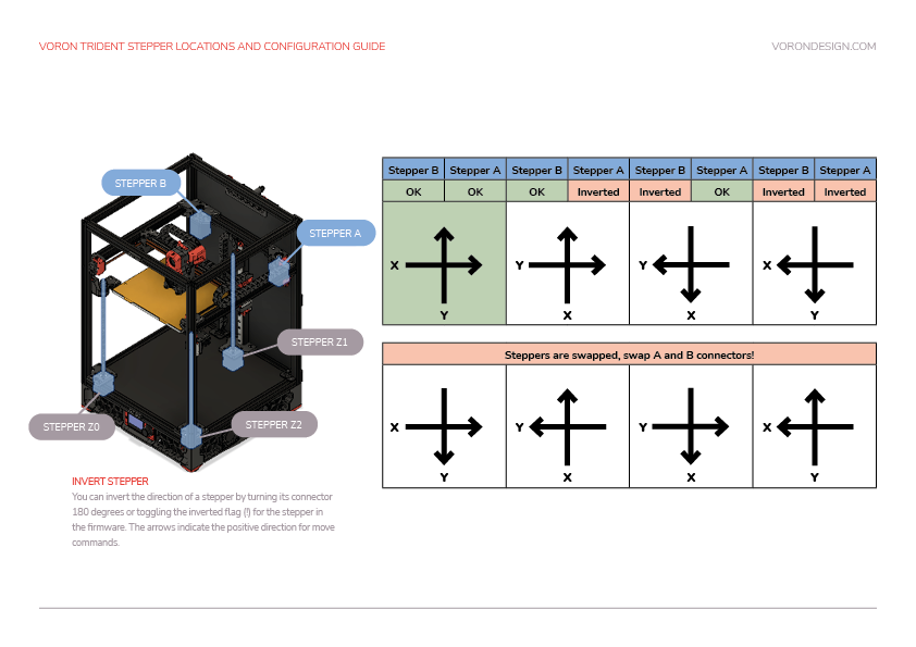
Motor Configuration Guide for the Voron Trident
Bed Leveling
Z Tilt
The Trident uses automated bed leveling using 3 motors. There is a macro Z_TILT_ADJUST built into Klipper for that function. It is very similar to the QUAD_GANTRY_LEVEL used by V2, but supports 3 or more motors. Run the Z_TILT_ADJUST and it will probe each of the 3 points 3 times, average the readings, then make adjustments until the gantry is level.
After that process has been completed, re-home z by running G28 Z.
Tilt with Heated Bed and Chamber
Set your bed temperature to 100C
This will be the first time that a Z_TILT_ADJUST has been run at a high chamber temperature. To ensure that the probe has stabilized with the heated bed at 100C run PROBE_ACCURACY with the nozzle at the center of the bed. If the values are trending (increasing or decreasing) throughout the 10 probes or the standard deviation is greater than 0.003mm, wait another 5 minutes and try again.
Once the readings are stable, run Z_TILT_ADJUST. Make a note of how long the probe readings took to stabilize for when starting prints - typically a cold printer takes 10-20 minutes to stabilize at temperature.
Stepper Motor Check
To verify that each stepper motor is operating correctly, send a command such as :
STEPPER_BUZZ STEPPER=stepper_x
The STEPPER_BUZZ command will cause the given stepper to move one millimeter in a positive direction and then it will return to its starting position. This movement cycle will repeat 10 times.
You will be looking for three things:
- Ensure that the motor which responds is the one you expected.
- Ensure that the motor moves cleanly: forward, pause, back, pause, repeat. Lack of movement, or vibrating or buzzing oddly are all cause for concern
- Ensure that the motor moves the correct direction first. If the movement is backwards, it is important to correct at this stage.
A single test of each motor is being used to confirm multiple aspects of its function: that the motor moves properly, that it’s the correct motor, and what direction it moves. Please make sure you confirm ALL stated expectations for each motor. You can repeat the test multiple times if needed.
Run this command for each of the motors:
| Command | Expectation |
|---|---|
| STEPPER_BUZZ STEPPER=stepper_x | The back left gantry motor will rotate clockwise first, then back counterclockwise |
| STEPPER_BUZZ STEPPER=stepper_y | The back right gantry motor will rotate clockwise first, then back counterclockwise |
| STEPPER_BUZZ STEPPER=stepper_z | the front left corner of the bed moves up, then back down |
| STEPPER_BUZZ STEPPER=stepper_z1 | the back left corner of the bed moves up, then back down |
| STEPPER_BUZZ STEPPER=stepper_z2 | The back right corner of the bed moves up, then back down |
| STEPPER_BUZZ STEPPER=stepper_z3 | The front right corner of the bed moves up, then back down |
| STEPPER_BUZZ STEPPER=extruder | The extruder moves. Direction will be tested later for this motor |
Troubleshooting
- If the stepper does not move at all
- Verify the
enable_pinandstep_pinin your printer.cfg. - Verify that the motor driver has power
- Verify the
-
If the stepper motor moves but does not return to its original position then verify the
dir_pinsetting. -
If the wrong motor moves, verify that the correct motors are plugged into the correct ports of the controller
-
If the stepper motor movement is backwards, then it generally indicates that the “dir_pin” for the axis needs to be inverted. Add a ‘!’ in front of the “dir_pin”, or remove it if already present. Example:
dir_pin: PA1->dir_pin: !PA1 -
If the load moves significantly more or significantly less than one millimeter then verify the
rotation_distancesetting. - If the motor buzzes without making clean 1mm movements, check the stepper motor wiring
XY Homing Check
At this point everything is ready to home X and Y.
Important: You need to be able to quickly stop the printer in case something goes wrong (e.g. the tool head goes the wrong direction). There are a few ways of doing this:
- Use the E-stop button on the display (if installed). On the Mini12864 it is the small button underneath the main control knob. Test the button and see what happens - Klipper should shut down. Raspberry Pi and OctoPrint/Mainsail/Fluidd should still be running but disconnected from Klipper. Press “Connect” in the upper left corner of OctoPrint, then in the Octoprint terminal window send a
FIRMWARE_RESTARTto get the printer back up and running. - Have a computer right next to the printer with the
RESTARTorM112command already in the terminal command line in OctoPrint. When you start homing the printer, if it goes in the wrong direction, quickly send the restart command and it will stop the printer. - As a “nuclear” option, power off the printer with the power switch if something goes wrong. This is not ideal because it may corrupt the files on the SD card and to recover would require reinstalling everything from scratch.
Once there is a tested process for stopping the printer in case of something going wrong, you can test X and Y movement. note: you will need to test X AND Y before you can correctly determine what adjustments are needed. First, send a G28 X command. This will only home X: The tool head should move up slightly and then move to the right until it hits the X endstop. If it moves any other direction, abort, take note, but still move on to testing Y. Next, test Y: run G28 Y. The toolhead should move to the back of the printer until it hits the Y endstop. In a CoreXY configuration, both motors have to move in order to get the toolhead to go in only and X or Y direction (think Etch A Sketch). If the gantry moves downward first before moving to the right, you must reverse your z stepper directions in the config.
If either axis does not move the toolhead in the expected or correct direction, refer to the table below to figure out how to correct it. If you need to invert the direction of one of the motors, invert the direction pin definition by adding a ! to the pin name. For example, dir_pin: PB2 would become dir_pin: !PB2. (if the entry already has a !, remove it instead). If the motors are going in directions that match the lower row of the chart, physically swap your X and Y (A and B) motor connectors on the MCU.
- [stepper x] = Motor B
- [stepper y] = Motor A
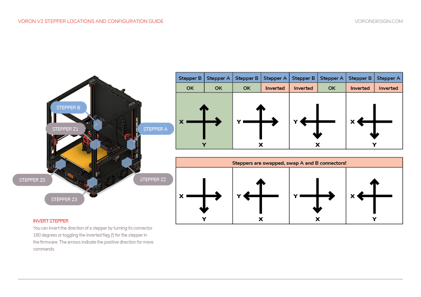
Motor Configuration Guide for the Voron V2
Bed Leveling
Quad Gantry Level
Since the V2 uses 4 independent Z motors, the entire gantry system must be specially levelled. The macro to call this process is QUAD_GANTRY_LEVEL (sometimes referred to in conversation as ‘QGL’). It will probe each of 4 points 3 times, average the readings, then make adjustments until the gantry is level.
If the process fails due to an “out of bounds” error, disable your stepper motors and slowly move your gantry or bed by hand until it is approximately flat. Re-home your printer (G28) and then rerun the sequence. You may have to run it more than once. Make sure that the adjustment value for each stepper motor converges to 0. If it diverges, check to make sure you have your stepper motors wired to the correct stepper driver (check documentation).
QGL with Heated Bed and Chamber
Run a G28 command to home the printer since a SAVE_CONFIG restarts the printer.
This will be the first time that a Quad Gantry Level has been run at a high chamber temperature. To ensure that the probe has stabilized with the heated bed at 100C and the hot end at 150C, run PROBE_ACCURACY with the nozzle at the center of the bed. If the values are trending (increasing or decreasing) throughout the 10 probes or the standard deviation is greater than 0.003mm, wait another 5 minutes and try again.
Once the readings are stable, run QUAD_GANTRY_LEVEL. Make a note of how long the probe readings took to stabilize for when starting prints - typically a cold printer takes 10-20 minutes to stabilize at temperature.
Common QGL Problems
- If the QGL is having issues with too high of a standard deviation and the printer is heated and stable, check Z belt tension. Make sure they are reasonably tight and even.
- If QGL fails with being unable to reach the probe in time, do a
FIRMWARE_RESTART, manually level the bed as closely as possible, then home (G28) and re-attempt.
Stepper Motor Check
To verify that each stepper motor is operating correctly, send a STEPPER_BUZZ command, such as:
STEPPER_BUZZ STEPPER=stepper_x
The STEPPER_BUZZ command will cause the given stepper to move one millimeter in a positive direction and then it will return to its starting position. This movement cycle will repeat 10 times.
You will be looking for three things:
- Ensure that the motor which responds is the one you expected.
- Ensure that the motor moves cleanly: forward, pause, back, pause, repeat. Lack of movement, or vibrating or buzzing oddly are all cause for concern
- Ensure that the motor moves the correct direction first. If the movement is backwards, it is important to correct at this stage.
A single test of each motor is being used to confirm multiple aspects of its function: that the motor moves properly, that it’s the correct motor, and what direction it moves. Please make sure you confirm ALL stated expectations for each motor. You can repeat the test multiple times if needed.
Run this command for each of the motors:
| Command | Expectation |
|---|---|
| STEPPER_BUZZ STEPPER=stepper_x | The left hand gantry motor will rotate counterclockwise first, then back clockwise |
| STEPPER_BUZZ STEPPER=stepper_y | The bed will move forward first, then return backward |
| STEPPER_BUZZ STEPPER=stepper_z | The right hand gantry motor will rotate counterclockwise first, then back clockwise |
| STEPPER_BUZZ STEPPER=extruder | The extruder moves. Direction will be tested later for this motor |
Troubleshooting
- If the stepper does not move at all
- Verify the
enable_pinandstep_pinin your printer.cfg. - Verify that the motor driver has power
- Verify the
-
If the stepper motor moves but does not return to its original position then verify the
dir_pinsetting. -
If the wrong motor moves, verify that the correct motors are plugged into the correct ports of the controller
-
If the stepper motor movement is backwards, then it generally indicates that the “dir_pin” for the axis needs to be inverted. Add a ‘!’ in front of the “dir_pin”, or remove it if already present. Example:
dir_pin: PA1->dir_pin: !PA1 -
If the load moves significantly more or significantly less than one millimeter then verify the
rotation_distancesetting. - If the motor buzzes without making clean 1mm movements, check the stepper motor wiring
Endstop Check
this document describes testing x and y endstops. if you will be using sensorless homing, test any physical endstops you do have, and refer to the sensorless homing guide.
Slowly move the toolhead and bed to the center, then send the QUERY_ENDSTOPS command. The terminal window should respond with the following:
Send: QUERY_ENDSTOPS

Recv: x:open y:open z:open
If either “X” or “Y” shows “triggered”, double-check to make sure none of them are pressed.
Next, move the toolhead all the way to the right until you hear a clicking sound, then send the QUERY_ENDSTOPS command again.
Make sure that the X endstop says “triggered” and the Y and Z endstops stay open.
Next, return the toolhead to the middle, and move the bed all the way forward. This should result in the Y endstop reading “triggered”
The Voron Switchwire, uses a “probe virtual endstop” for Z, so the Z endstop will be dealt with in a later step
Troubleshooting
-
If one of the endstops acts backwards (reading “TRIGGERED” when open and vice-versa), go into the printer configuration file (typically printer.cfg) and add or remove the ! in front of the pin identifier. For example, if the X endstop was inverted, add a ! in front of the pin number as follows:
endstop_pin: P1.28->endstop_pin: !P1.28
Be warned however: All stock Voron endstops are N.C. switches connected to GND. If a stock endstop requires!it may indicate a wiring issue -
If the endstop cannot be reached with the toolhead, make sure that you don't have any rubber rail stoppers left on the rail.
-
If there are no rubber rail stoppers in place and you still can't trigger the endstop, make sure that your gantry is deracked. Gantry deracking
- if a switch seems “slow” to respond, you may need to add a software controlled pullup to its pin, using
^. Most controllers in Vorons have hardwired pullups, and do not require this, but there are always exceptions.
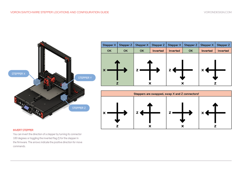
XY Homing Check
At this point everything is ready to home X and Y.
You need to be able to quickly stop the printer in case something goes wrong (e.g. the tool head goes the wrong direction). There are a few ways of doing this:
- Use the E-stop button on the display (if installed). On the Mini12864 it is the small button underneath the main control knob. Test the button and see what happens - Klipper should shut down. The Raspberry Pi and OctoPrint/Mainsail/Fluidd should still be running but disconnected from Klipper.
- Have a computer right next to the printer with the
RESTARTorM112command already in the terminal command line. When you start homing the printer, if it goes in the wrong direction, quickly send the restart command and it will stop the printer.- As a “nuclear” option, power off the printer with the power switch if something goes wrong. This is not ideal because it may corrupt the files on the SD card and to recover would require reinstalling everything from scratch.
After a shutdown, press the FIRMWARE_RESTART button in Mainsail or Fluidd to resume normal operation
After a shutdown, press “Connect” in the upper left corner of OctoPrint. Next, in the Octoprint terminal window send a FIRMWARE_RESTART to get the printer back up and running.
Once there is a tested process for stopping the printer in case of something going wrong, you can test X and Y movement.
First, test Y: run G28 Y. The toolhead should move up slightly, and then the bed should move forward until it triggers the Y endstop. If the bed moves the wrong direction, you probably need to invert its dir_pin.
In a CoreXZ configuration, two motors motors work together to move the printer in X and Z (think Etch A Sketch). As a result, you need to look at something that was supposed to be an X move, AND something that was supposed to be a Z move to fully identify problems.
Next, send a G28 X command. This will only home X: The toolhead should move up slightly and then move to the right until it hits the X endstop.
Finally, send a G28 Z command. Note that this will actually force homing all axes. So:
- The toolhead will lift slightly
- The toolhead will home to the right
- The bed will home to the front
- The toolhead and bed (X and Y axes) will return to center
- The toolhead will move down, and home to the bed, using the probe
- If the toolhead moves differently than expected, use the chart below to correct it.
- If the bed moves unexpectedly, this probably means the Y motor is swapped with one of the X/Z motors.
If the x or z axis does not move the toolhead in the expected or correct direction, refer to the table below to figure out how to correct it. If you need to invert the direction of one of the motors, invert the direction pin definition by adding a ! to the pin name. For example, dir_pin: PB2 would become dir_pin: !PB2. (if the entry already has a !, remove it instead). If the motors are going in directions that match the lower row of the chart, physically swap your X and Y (A and B) motor connectors at the MCU.
Motor Configuration Guide for the Voron Switchwire
Z Endstop Pin Location
Some dockable probe users choose to use their probe as a “z virtual endstop”, and thus will not have a z endstop to locate. If this is you, you probably just want to use the coordinates of the center of your bed for this step. Also note that these coordinates will likely be in your “klicky macros”, rather than the locations mentioned below.
As a Tap user, you do not actually have a z endstop to locate. Instead, simply set the [homing_override] or [safe_z_home] coordinates to the center of your bed
- Start by re-running
G28 X Yto home X and Y. - Using the software controls, move the nozzle until it is directly over the Z endstop switch.
- Send an
M114command and record the X and Y values. - Update the homing routing in the printer configuration file under [homing_override] or [safe_z_home] with those values.
- Restart Klipper with
FIRMWARE_RESTART. - Run a full
G28and make sure that the printer properly homes X, Y, and Z.
Probe Check
If you haven’t already, this is probably a good time to get your dockable probe up and running, including picking up out of the dock. If you are using klicky macros, there is documentation here. You should NOT enable the klicky meshing module at this time: that will come later.
Probe Testing
With the toolhead in the center of the bed, reconfirm that the probe is working correctly.
When it is far from the bed, QUERY_PROBE should return “open”. When a metal object is close to the probe, QUERY_PROBE should return “triggered”. If the signal is inverted, add a “!” In front of the pin definition (ie, pin: ! z:P1.24 ).
Slowly reduce your Z height and run QUERY_PROBE each time until QUERY_PROBE returns “triggered” - make sure the nozzle is not touching the print surface (and has clearance).
There are 3 states to test with your dockable probe:
- Probe not attached: a. Remove the probe from the toolhead. b. run
QUERY_PROBE. It is expected to return “triggered” - When the probe is attached, but not triggered. a. Attach the probe to the toolhead b. run `QUERY_PROBE. It is expected to return “open”
- When the probe is attached, and triggered. a. Keep the probe attached to the toolhead b. activate the probe switch with your finger, and while keeping the switch pressed, c. run
QUERY_PROBE. It is expected to return “triggered”
There are software configuration instructions for Tap, including an important activation macro located here. Note that without this macro, it is likely you will accidentally hit your bed with a fully heated hotend, and ruin your PEI.
Test that when the toolhead is in its normal (down) position, QUERY_PROBE indicates “open”, and when the toolhead is lifted slightly, QUERY_PROBE indicates “triggered”
Probe Accuracy Check
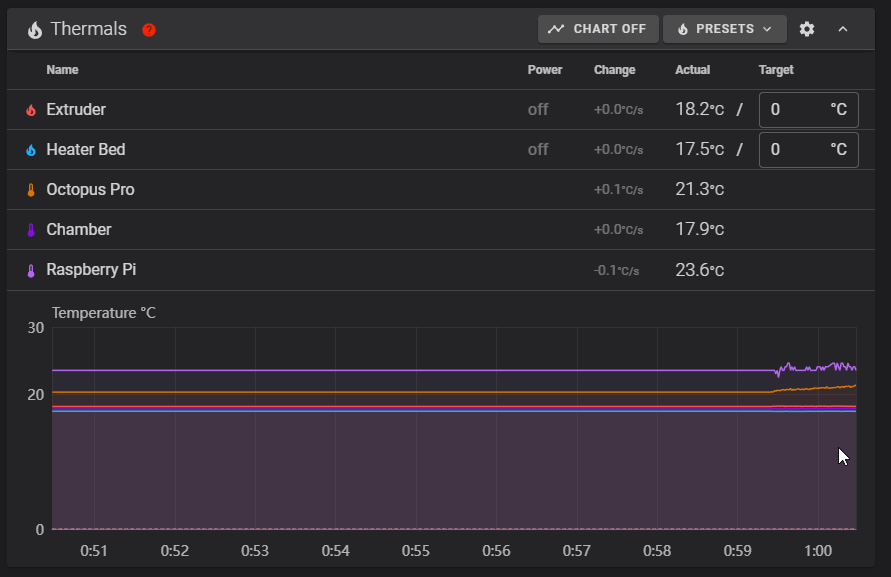
With the bed and hotend cold (for now), move the probe to the center of the bed and run PROBE_ACCURACY. It will probe the bed 10 times in a row and output a standard deviation value at the end. Make sure that the sensed distance is not trending (gradually decreasing or increasing over the 10 probes) and that the standard deviation is less than 0.003mm.
Example of unstable PROBE_ACCURACY (trending downward during warm up).
Send: PROBE_ACCURACY
Recv: // PROBE_ACCURACY at X:125.000 Y:125.000 Z:7.173 (samples=10 retract=2.000 speed=2.0
Send: M105
Recv: // probe at 125.000,125.000 is z=4.975000
Recv: // probe at 125.000,125.000 is z=4.960000
Recv: // probe at 125.000,125.000 is z=4.955000
Recv: // probe at 125.000,125.000 is z=4.952500
Recv: // probe at 125.000,125.000 is z=4.950000
Recv: // probe at 125.000,125.000 is z=4.947500
Recv: // probe at 125.000,125.000 is z=4.942500
Recv: // probe at 125.000,125.000 is z=4.937500
Recv: // probe at 125.000,125.000 is z=4.937500
Recv: // probe at 125.000,125.000 is z=4.932500
Recv: // probe accuracy results: maximum 4.975000, minimum 4.932500, range 0.042500, average 4.949000, median 4.948750,
standard deviation 0.011948
Troubleshooting
- If the probe is stuck always showing triggered (or always open) It is typically indicitive of a wiring issue:
- Make sure that the physical wiring has (G)round, (S)ignal, and (V)oltage correctly connected
- If there is a jumper to select the supply voltage for your probe, make sure it is set correctly
- Make sure the klipper
[probe] pin:matches where your probe is actually connected
- If the probe is trending one direction or the other in the accuracy check, it is typically indicitive of a mechanical issue
- Check grub screws on the z drives
- check z belt tension (if applicable)
- if all else fails, try reducing the
[Probe] speed:
Probe Calibration
Although we’ve already tested the probe, the probe has not yet been calibrated, this means that it is just blindly treating the position where the probe activates as z=0, which almost certainly not correct.
Note: Users of Beacon, Cartographer, or the Btt Eddy Probe should follow the calibration instructions from their respective manufacturers, and skip this process.
- Home the printer:
G28 - Move the toolhead to the center of the bed. For a 300mm printer, that command might be:
G0 X150 Y150 F6000. Adjust as necessary for your build - run the command
probe_calibrate - if you are using a dockable probe, such as klicky, you will now need to remove the probe from the toolhead by hand.
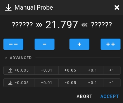
- Conduct “the paper test”:
- Place a piece of typical printer paper on the bed.
- Using either the testz command as shown in the console, or the “Manual Probe” popup in mainsail/fluidd, move the toolhead down until you start to feel resistance from the nozzle against the piece of paper.
- execute the command
accept, or press the “accept” button - execute the command
save_config. Klipper will then restart, saving the new calibration.
When moving in small increments during the paper test, klipper will use a back & forth motion, which is intended to negate back lash issues during the test. Don’t worry! we promise, after the back and forth is complete, the end delta is the distance you requested. It just went the long way to get there.
Define 0,0 Point
The homing position is not at the typical location of 0,0 but at the maximum travel location. The actual numbers vary by printer build size.
- In all Vorons, we use standard cartesian coordinates. This means that when you see a number like 0,0, the first number represents left/right movement, and the second number represents forward/back movement.
- It is also accepted practice that 0 is at the LEFT, and 0 is at the FRONT. So when we refer to the 0,0 point, we are referring to the nozzle of the printer being located at the front left corner of the bed.
- This point is used as a common reference between you, your slicer, and your printer. Without consensus on where this point is, you’ll have a variety of strange problems.
Depending on bed location, the positional parameters may need to be adjusted to re-locate the 0,0 point.
- Test that the toolhead is physically capable of reaching the front left corner of the bed.
- Run
M84to turn off the motors - gently move the toolhead by hand to the front left.
- If you encounter resistance before the nozzle gets close to the front left corner, consider:
- Is a mechanical problem stopping the toolhead before it should? If so, you may need to go back to earlier build steps, such as “deracking”.
- Is your bed oversized? If, for example, you have a 320mm bed on a 300mm build, it’s perfectly reasonable that there be some extra build plate that you can’t actually reach
- Otherwise, you may need to physically adjust the placement of your bed.
- Run
- Run
G28 X Yto home X and Y. After this, the nozzle will be at the position defined asposition_endstopunder[stepper_x]and[stepper_y]. In Vorons, this will generally be the same asposition_max - Using the OctoPrint or Mainsail controls, move the toolhead to 0,0
- Pay attention as the toolhead is moving. If there is any skipping as it gets near the corner, you will need to stop and deal with that before continuing
- This may indicate a racked gantry, or other belting issue
- It may be that, for one reason or another, your printer simply has slightly less travel than stock:
- Rehome, with
G28 X Y - Move the X and Y axes one at a time to 0 to determine which one is the problem
- Reduce
position_endstopANDposition_maxfor that axis until the problem goes away
- Rehome, with
- Once the toolhead is able to reach 0,0 cleanly, inspect how close it is to the front left corner of the bed
- Note: Due to other tolerances, it is usually not recommended to have the 0,0 exactly on the corner of the bed or build surface. Spec bed sizes are always slightly larger than the defined print volume so print volume loss will be minimal.
- if the nozzle is above the bed, within 5 mm of the edge, perfect. Move on.
- for each axis, if the nozzle is too far in to the bed, INCREASE
position_endstopandposition_max. For example, to move the 0,0 point 2mm to the left, you would add 2mm to[stepper_x]position_endstopANDposition_max. - if the nozzle is out beyond the bed, DECREASE
position_endstopandposition_max. For example, to move the 0,0 point 2mm back, you would subtract 2mm from[stepper_y]position_endstopANDposition_max.
If the Z endstop pin location has already been set in klipper, be sure to re-adjust these coordinates any time you recalibrate the x or y endstop.
If anything is updated in the printer configuration file, save the file and restart Klipper using FIRMWARE_RESTART.
Bed Locating
If you are using your dockable probe as a “virtual z endstop”, you do not require the stock z endstop. On a Trident, no action is required for this step. On a Voron 2, the bed placement may be adjusted by moving the toolhead as far forward as possible (by hand) and then sliding the bed until it is just slightly under the nozzle
As tap is used as a “virtual z endstop”, your printer does not require the installation of the stock Z endstop. On a Trident, no action is required for this step. On a Voron 2, the bed placement may be adjusted by moving the toolhead as far forward as possible (by hand) and then sliding the bed until it is just slightly under the nozzle
Before the 0,0 point and Z endstop locations are set in software, the physical locations of the Z endstop and print bed need to be finalized.
The Z endstop should be located close to max Y position.
- Home X and Y with
G28 X Y - Move the toolhead to the left until the nozzle is in line with the z endstop.
- Move the Z endstop along the extrusion until the endstop is centered directly under the nozzle
- Secure the Z endstop in this position
On a V2, the bed should now be adjusted so there is a small (2-3mm) gap between the back edge of the bed, and the shaft of the Z endstop.
Endstop Check
this document describes testing all 3 endstops. if you will be using sensorless homing on x and/or y, test any physical endstops you do have, and refer to the sensorless homing guide.
Your motors should not be energized for this step, as you will be moving the toolhead by hand. If they are energized, run M84 to power down the motors.
By hand, slowly move the toolhead to the center, then send the QUERY_ENDSTOPS command. The terminal window should respond with the following:
Send: QUERY_ENDSTOPS

Recv: x:open y:open z:open
If any of them say “triggered” instead of “open”, double-check to make sure none of them are pressed. Next, move the toolhead all the way to the right until you hear a clicking sound, then send the QUERY_ENDSTOPS command again.
Make sure that the X endstop says “triggered” and the Y and Z endstops stay open.
Move the toolhead back to center and repeat with the Y endstop by moving the gantry all the way to the back.
Some dockable probe users choose to use their dockable probe as a “virtual endstop”. If you are one of these users, You may ignore the z endstop for now. It will be attended to in a later step, when you test the probe
Tap acts as a “virtual endstop”. This functionality will be tested in a later step, so the Z endstop may be safely ignored for now.
To check the Z endstop, manually press the z endstop until you hear a clicking sound. Check with QUERY_ENDSTOPS whether the endstop works.
Troubleshooting
-
If one of the endstops acts backwards (reading “TRIGGERED” when open and vice-versa), go into the printer configuration file (typically printer.cfg) and add or remove the ! in front of the pin identifier. For example, if the X endstop was inverted, add a ! in front of the pin number as follows:
endstop_pin: P1.28->endstop_pin: !P1.28
Be warned however: All stock Voron endstops are N.C. switches connected to GND. If a stock endstop requires!it may indicate a wiring issue -
If the endstop cannot be reached with the toolhead, make sure that you don't have any rubber rail stoppers left on the rail.
-
If there are no rubber rail stoppers in place and you still can't trigger the endstop, make sure that your gantry is deracked. Gantry deracking
- if a switch seems “slow” to respond, you may need to add a software controlled pullup to its pin, using
^. Most controllers in Vorons have hardwired pullups, and do not require this, but there are always exceptions.
PID Tune Bed & Hotend
The PID tune is important for tuning the printer for a given hardware configuration to ensure that temperatures can remain as stable as possible during operation.
PID Tune Heated Bed
Move nozzle to the center of the bed and approximately 5-10mm above the bed surface, then run:
PID_CALIBRATE HEATER=heater_bed TARGET=100
It will perform a PID calibration routine that will last about 10 minutes. Once it is finished, type SAVE_CONFIG which will save the parameters into your configuration file.
PID Tune Hotend
Set the part cooling fans to 25% (M106 S64) and then run:
PID_CALIBRATE HEATER=extruder TARGET=245
It will perform a PID calibration routine that will last about 5 minutes. Once it is finished, type SAVE_CONFIG which will save the parameters into your configuration file.
Z Offset Adjustment
Initial / Simple Process
Preparation
Run a G28.
- Move the nozzle to the center of the bed if it is not already.
Run PROBE_CALIBRATE
With Dockable probes, some users choose to use the probe as their Z endstop, and others choose to use the stock Z endstop. If you have chosen to use the stock endstop, you will use the Z_ENDSTOP_CALIBRATE command, as shown in this guide. If you are using the Probe as your Z endstop, you should substitute the PROBE_CALIBRATE command
Run Z_ENDSTOP_CALIBRATE
Run Z_ENDSTOP_CALIBRATE
Slowly move the nozzle toward the bed by using TESTZ Z=-1 until the nozzle is relatively close to the bed, and then stepping down with TESTZ Z=-0.1 until the nozzle touches a piece of paper on top of the build plate. If you go too far down, you can move the nozzle back up with: TESTZ Z=0.1. Once you are satisfied with the nozzle height, run ACCEPT and then SAVE_CONFIG.
Important: Klipper assumes that this process is being done cold. If being performed hot, do an additional TESTZ Z=-0.1 before accepting.
If an “out of bounds” error occurs, send PROBE_CALIBRATE, ACCEPT, and then SAVE_CONFIG. This will redefine the 0 bed height so you will be able to get closer.
Fine Tuning Z Height
LCD Screen
The Z offset can be adjusted during a print using the Tune menu on the display, and the printer configuration can be updated with this new value. Remember that higher values for the position_endstop means that the nozzle will be closer to the bed. These changes will be temporary: it will be discarded when you restart klipper, unless you save it with the z_offset_apply_probe command.
Mainsail and Fluidd
The “babystepping” (“Z Offset”) controls may be used to fine tune the z offset. These changes are temporary: they will be discarded unless you press the save button, or use the z_offset_apply_probe command.
Last Resort
If all else fails, you can locate the [probe] z_offset in your config file, and adjust it by hand. A positive change will result in more squish, negative in less squish. be careful You don’t want to damage your bed.
If an “out of bounds” error occurs, send Z_ENDSTOP_CALIBRATE or ` PROBE_CALIBRATE, ACCEPT, and then SAVE_CONFIG. This will redefine the 0 bed height so you will be able to get closer.
Fine Tuning Z Height
LCD Screen
The Z offset can be adjusted during a print using the Tune menu on the display, and the printer configuration can be updated with this new value. Remember that higher values for the position_endstop means that the nozzle will be closer to the bed. These changes will be temporary: it will be discarded when you restart klipper, unless you save it with the z_offset_apply_endstop or z_offset_apply_probe command.
Mainsail and Fluidd
The “babystepping” (“Z Offset”) controls may be used to fine tune the z offset. These changes are temporary: they will be discarded unless you press the save button, or use the z_offset_apply_endstop or z_offset_apply_probe command.
Last Resort
If all else fails, you can locate the [stepper_z] position_endstop or [probe] z_offset in your config file, and adjust it by hand. A positive change will result in more squish, negative in less squish. be careful You don’t want to damage your bed.
If an “out of bounds” error occurs, send Z_ENDSTOP_CALIBRATE, ACCEPT, and then SAVE_CONFIG. This will redefine the 0 bed height so you will be able to get closer.
Fine Tuning Z Height
LCD Screen
The Z offset can be adjusted during a print using the Tune menu on the display, and the printer configuration can be updated with this new value. Remember that higher values for the position_endstop means that the nozzle will be closer to the bed. These changes will be temporary: it will be discarded when you restart klipper, unless you save it with the z_offset_apply_endstop command.
Mainsail and Fluidd
The “babystepping” (“Z Offset”) controls may be used to fine tune the z offset. These changes are temporary: they will be discarded unless you press the save button, or use the z_offset_apply_endstop command.
Last Resort
If all else fails, you can locate the [stepper_z] position_endstop in your config file, and adjust it by hand. A positive change will result in more squish, negative in less squish. be careful You don’t want to damage your bed.
Z Offset Adjustment
The Switchwire uses its probe as the Z endstop, which you have already calibrated. However, you may find that some fine tuning is still required. There are various ways you can do this:
LCD Screen
The Z offset can be adjusted during a print using the Tune menu on the display, and the printer configuration can be updated with this new value. Remember that higher values for the position_endstop means that the nozzle will be closer to the bed. These changes will be temporary: it will be discarded when you restart klipper, unless you save it with the z_offset_apply_probe command.
Mainsail and Fluidd
The “babystepping” (“Z Offset”) controls may be used to fine tune the z offset. These changes are temporary: they will be discarded unless you press the save button, or use the z_offset_apply_probe command.
Last Resort
If all else fails, you can locate the [probe] z_offset in your config file, and adjust it by hand. A positive change will result in more squish, negative in less squish. be careful You don’t want to damage your bed.
Looks like you are done with the initial startup guide for your brand new printer!
But wait! There’s more:
Extruder Calibration (e-steps)
Before the first print, make sure that the extruder extrudes the correct amount of material.
- With the hotend at temperature, make a mark on the filament between the roll of filament and your extruder, between 120mm and 150mm away from the entrance to the extruder. Measure the distance from the entrance of the extruder to that mark.
- In Octoprint / Mainsail, extrude 50mm 2 times (for a total of 100mm since Klipper doesn’t allow you to extrude more than 50mm at a time).
- Measure from the entrance of your extruder to the mark you made previously.
- In a perfect world, assuming the mark was at 120mm, it would measure 20mm (120mm - 20mm = 100mm), but usually won’t be.
- Update
rotation_distancein the extruder section of the configuration file using this formula:- New Config Value = Old Config Value * (Actual Extruded Amount/Target Extruded Amount)
You can also use the calculator here
Note: a higher configuration value means that less filament is being extruded.
Paste the new value into the configuration file, restart Klipper, and try again. Once the extrusion amount is within 0.5% of the target value (ie, 99.5-100.5mm for a target 100mm of extruded filament), the extruder is calibrated!
Please adjust your rotation_distance in the extruder section according to the following table. If you are building Stealthburner with its corresponding Extruder, you are looking for Clockwork2.
| Extruder | Gear Ratio | Rotation Distance |
|---|---|---|
| Clockwork1 | 50:17 | 22.6789511 |
| Clockwork2 | 50:10 | 22.6789511 |
| Galileo2 | 9:1 | 47.088 |
| Mobius 3 and 4 | 80:20 | 22.6789511 |
A Raspberry Pi is like a computer. Please shut it down appropriately using your webinterface’s shutdown button.
It is also strongly recommended to make regular backups of your printer.cfg and other config files.