Voron V2 - FLY FLYF407ZG Wiring
Initial Preparation
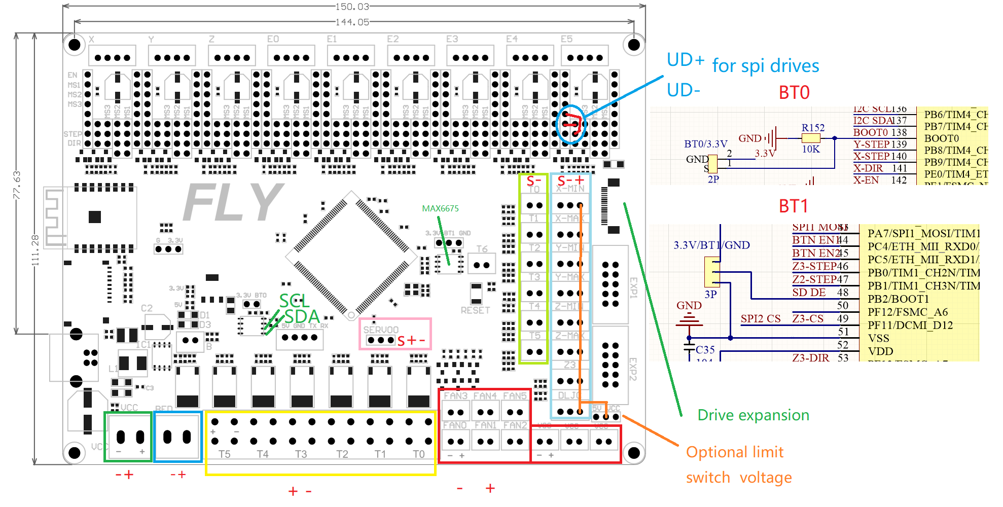
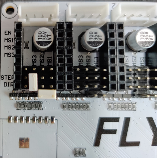
- Remove all jumpers from the board. Install just the jumpers as shown.
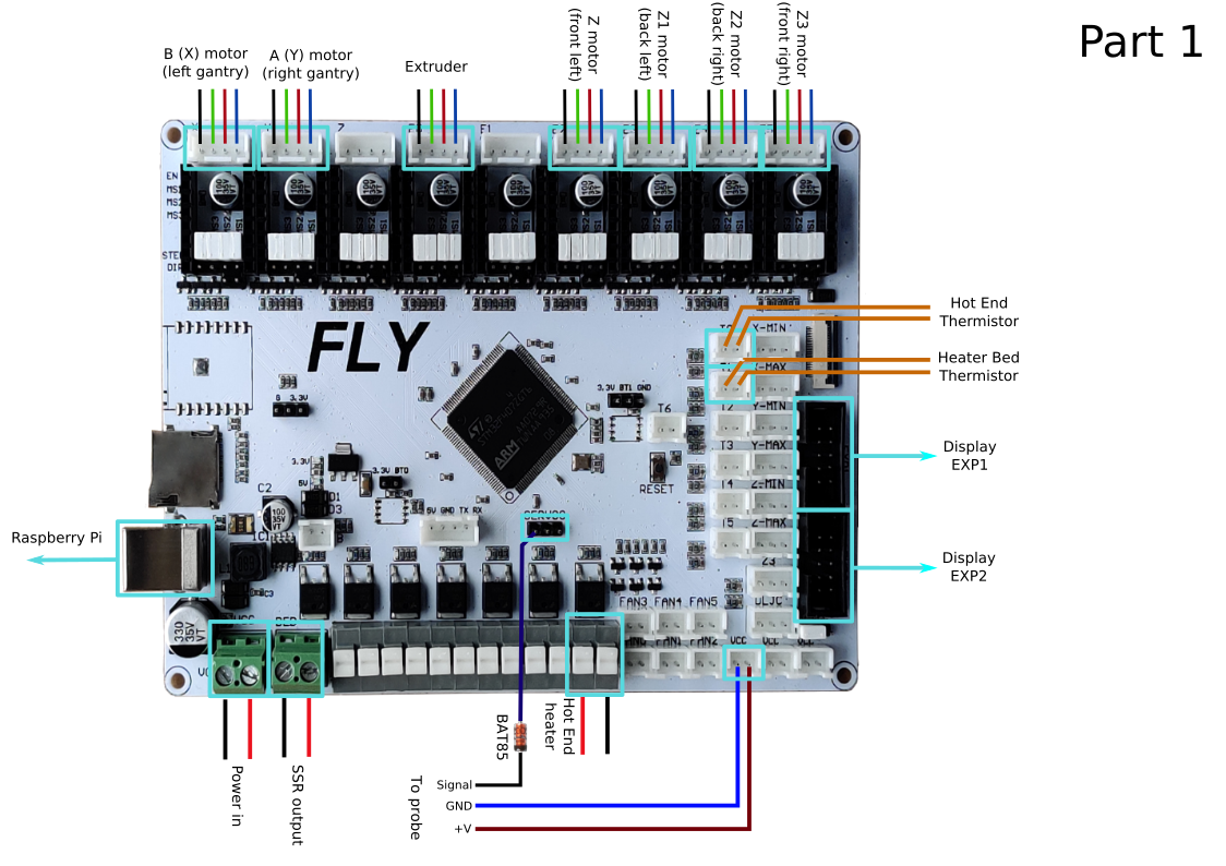
MCU Part 1
- Place stepper drivers for X, Y, E, Z, Z1, Z2, and Z3 in positions X, Y, E0, E2, E3, E4, E5
- Plug in stepper motors for X, Y, E, Z, Z1, Z2, and Z3 in positions X, Y, E0, E2, E3, E4, E5
- Plug Hot End thermistor to thermistor T0
- Plug Hot End heater in to HEATER T0
- Plug Bed Heater thermistor in to T1
- Plug SSR Control for Heated Bed in to BED
- Plug Probe PWR and GND into VCC
- Plug Probe Signal (with BAT85 diode) in to SERVO0, pin 1 (toward USB)
- Wire 24V and 0V from DC power supply to Power In
- Connect USB Cable to your FLYF407ZG, but do not connect it yet to your Raspberry Pi
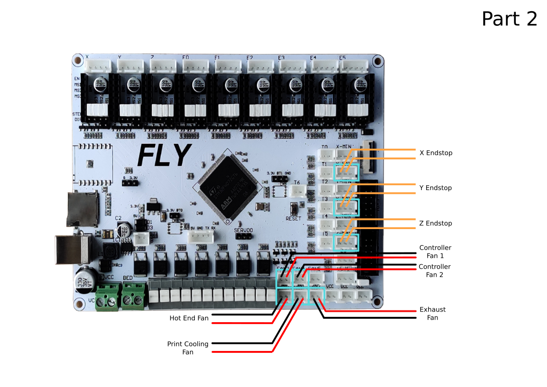
MCU Part 2
- Plug Hot End Fan in to FAN0
- Plug Part Cooling Fan in to FAN1
- Connect X end stop to X-MAX connector
- Connect Y end stop to Y-MAX connector
- Plug in Exhaust Fan in to FAN3
- Plug in Controller Fan 1 in to FAN4
- Plug in Controller Fan 2 in to FAN5
- Plug Z Endstop Switch into Z-MAX
- Plug display wires in to EXP1 and EXP2
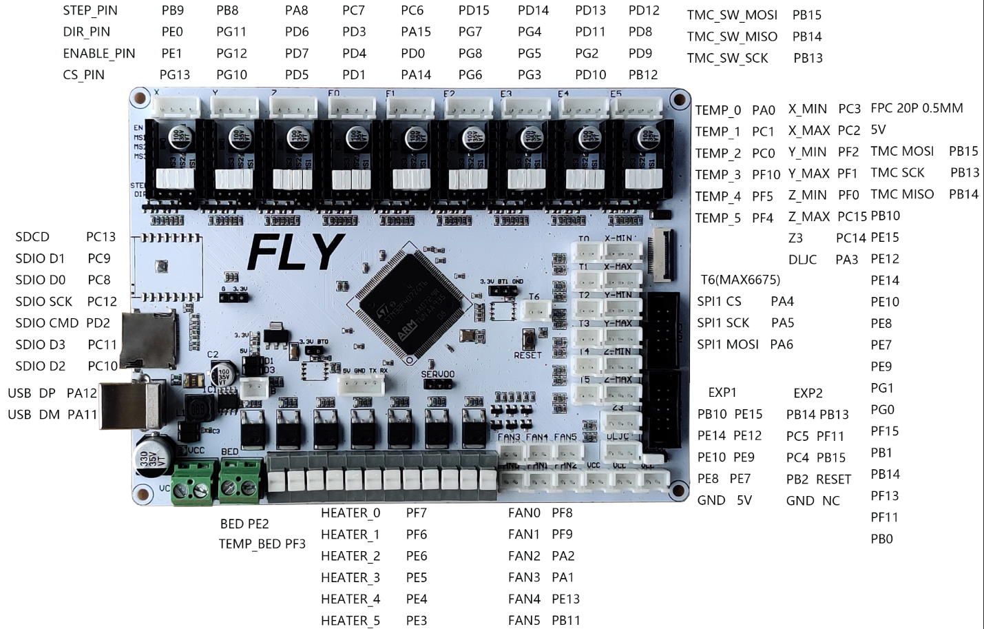
Pinout
For reference, here is the pinout of the FLYF407ZG